
The Duggan Steel Group, incorporating Duggan Steel (Irl) Ltd and Duggan Profiles & Steel Service Centre Ltd, was established in 1976. Operating from three factories in Kilkenny and a depot in Bandon, Co. Cork we supply steel construction components to both the Agricultural and Industrial sectors. Our aim is to provide excellent service and quality products at competitive prices.
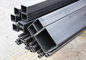
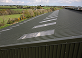
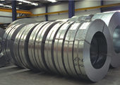
Duggan Steel (Irl) Ltd is the steel stockholding division of the Group. Its activities include the sale of structural steel sections and general steel products such as rebar, weld mesh and flow forge. A shot blasting and priming service is also available. Duggan Profiles & Steel Service Centre Ltd is involved in the manufacture and supply of a wide range of steel building components including profiled steel sheeting, purlin and rail systems and a comprehensive range of associated ancillary products.