


![]()
General Information:
Tie Ropes are an anti sag component which may be used in roof or wall situations to transfer a portion of purlin or rail loading to the rafters or stanchions. Tensioning of the rope is achieved by tightening the nut on the eyebolt at the upper end. To examine the above in closer detail select the 3D option above.
The diagram below illustrates a Tie Rope assembly. The “LENGTH” dimension is to customer requirements while all other measurements are standard. Within reason there are no limits on how long or short Tie Ropes can be made.
Typical connection details are included in the section Applications and connection configurations later on this page. For guidance on the selection of suitable anti sag systems please refer to the sections Anti Sag Systems.
Applications and connection configurations:
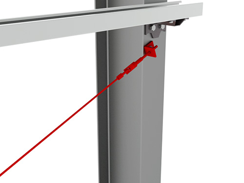
Connection to stanchion or rafter for anti sag
![]()
The Tie Rope is mounted off the stanchion or rafter by means of a bolted connection as shown. A tensioning nut on the eyebolt provides a means of tensioning the rope after installation. The standard mounting positions for the Tie Rope are 140mm from the face of the cleat and 35mm off centre of support member.
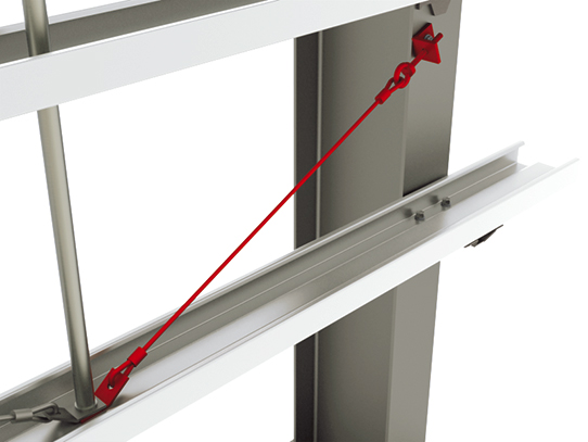
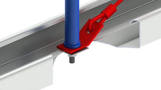
Single Tie Rope connection to purlin or rail for anti sag support
![]()
The image above illustrates the connection arrangement where cold-rolled sections (ProSigma+ or Cee) are supported by rows of Tube Struts and a single Tie rope per run. Whereas the use of Tie Ropes is most commonly associated with side rails the connection details referred to here can equally be applied with purlins. More detailed guidance on the appropriate use of anti sag systems is included in the section Anti Sag Systems.
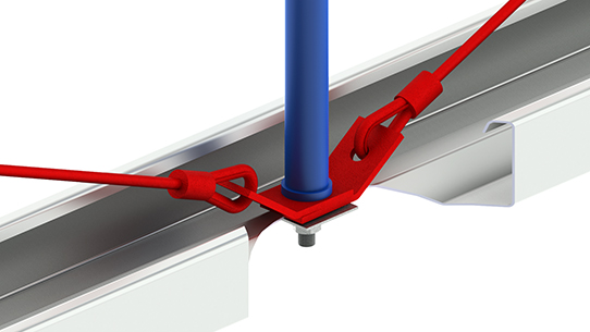
Double Tie Rope connection to purlin or rail for anti sag support
![]()
This type of connection is common on narrower bays where a single row of Tube Struts is used. It may be applied in roof or wall situations.
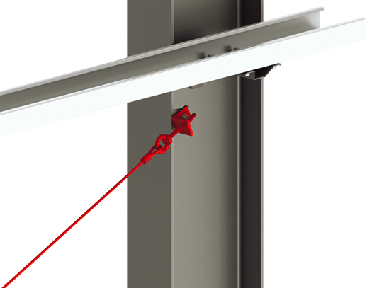
Connection of Tie Rope to corner stanchion
![]()
In cases where the Tie Rope cannot be fixed to the face of the hot rolled member a suitable alternative fixing support must be provided by the fabricator. A typical example is the case shown above where the rope must connect to the web of the stanchion. An angle tab is fixed to the inner face of the flange and acts as a mounting support for the Tie Rope. This may be observed more clearly by selecting the 3D view option. The Tie Rope is similar in all respects to that used in all other situations.
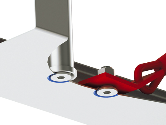
Connection of Tie Tope to counterformed sections
![]()
In certain situations, framing around windows, doors etc., it may be necessary to provide flush finish outer surfaces. To avoid obstructions caused by protruding bolt heads Counterforming may be used in conjunction with the use of countersunk head bolts. The image above shows how Tie Ropes are fitted in such situations. The Tie Rope is offset away from the Tube Strut and mounted on top of the counterformed hole (shown in blue). It is secured in place using a countersunk head bolt. Whilst relatively unimportant the offset distance used is generally 70mm. This connection detail may be observed more clearly by selecting the 3D view option. The Tie Rope is similar in all respects to that used in all other situations.
Load data:
Duggan Profiles Tie Ropes have been tensile tested to EN1993-1-3 to determine their range of use. The working load in tension when used as indicated is 14.6kN.
How to order:
Product codes are used to uniquely identify all products and these should be used when ordering. The code for this product along with a drawing and CAD file are included in the table below. The quantity required along with the length as indicated on the drawing must also be provided.
ProSigma+ Tie Rope product code and drawings
| Code: | Description: | PDF File | |
| DP-DTW | Diagonal Tie Wire |